
The term “tolerance” originates from the Latin word “tolerare”, meaning to endure, withstand, or bear. In everyday language, it often describes the acceptance of different beliefs, religions, cultures, worldviews, or behaviors. In technical contexts, however, tolerance refers to the permissible variation in dimensions or parameters within a technical system.
Tolerance plays a key role in precision engineering, mechanical engineering, and in the production of semi-finished goods and components such as pipes, hoses, and rubber plates – and is clearly defined by standards.
What Does Tolerance Mean in Engineering?
The dimensions of a component are defined before production and called nominal values. During manufacturing, the actual dimensions of the finished part typically differ from these nominal values.
Tolerance is the allowed range between the maximum and minimum deviation from the nominal value that maintains component functionality. Tolerances may be defined as custom tolerances, general tolerances, or ISO tolerances.
Reasons for dimensional deviations include worn bearings and guides, tool wear, or changing environmental conditions such as temperature, pressure, or humidity. To keep components functional and interchangeable, their dimensions must remain within an allowable tolerance range.
Custom Tolerances
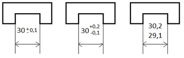
Custom tolerances can be expressed either as deviations from the nominal value (minimum and maximum) or as limit dimensions (upper and lower limits), as illustrated in the image.
If the deviations are the same, a symmetrical indication such as ±0.1 is placed after the nominal dimension (left image). If the deviations differ, the larger value appears on top, the smaller below (middle image). For limit dimensions, the maximum limit is placed above, and the minimum below (right image).
General Tolerances According to ISO 2768
General tolerances are specified in ISO 2768, which was originally published in 1991.
Part 1 of the standard includes tolerance tables for linear and angular dimensions. These are divided into four tolerance classes: fine (f), medium (m), coarse (g), and very coarse (v). “Fine” represents the class with the smallest permissible deviations from the nominal value.
It is used in precision mechanics, while the medium class is applied in mechanical and automotive engineering, for example for standard elements in drive systems. The coarse class is used in foundry technology and the production of semi-finished products. The very coarse class is rarely used today, as modern manufacturing processes typically achieve higher precision.


Along with tolerance classes, the tables also define limit deviations for various nominal size ranges. The smallest range applies to lengths up to 0.5 mm, and the largest from 4000 to 8000 mm. As lengths increase, the permitted tolerance range also becomes wider. For instance, the limit deviation for 0.5 mm is ±0.05 mm, and for 1000 to 2000 mm it is ±0.5 mm. In technical drawings, specific tolerance values are replaced by a reference to the applicable standard and a letter indicating the tolerance class, such as ISO 2768-m.
Part 2 of ISO 2768 includes tables for straightness and flatness, perpendicularity, symmetry, circular and planar run-out, roundness, and parallelism. Tolerance classes are identified by the letters H, K, and L, where H represents the tightest tolerance and L the widest.
ISO Tolerances
ISO 286 for Fits Involving Shafts and Bores
ISO tolerances for fits between parts such as shafts and holes are specified by ISO 286. These codes consist of a nominal value followed by a letter (for the tolerance position) and a number (for the tolerance grade) — for example, 30h6 or 30H6. Lowercase letters are used for the outside dimension of a shaft; uppercase for the inside dimension of a hole. For shafts marked with the letter “h”, the maximum dimension equals the nominal value. If the maximum is smaller than the nominal, letters from “g” down to “a” are used; if it’s larger, the letters “i” through “z” are used.

ISO 286 defines 20 tolerance grades with specific numerical values. The smallest grade is 01, followed by 0, 1, 2, up to 18. The higher the number, the greater the permitted deviation. Grades 01 to 4 are used for gauges or fine machining processes such as lapping or honing. Parts in mechanical and automotive engineering, and processes like milling, turning, and grinding, are generally manufactured to grades 5 to 11. Less precise methods such as pressing, casting, and rolling — commonly used for semi-finished products — typically fall within grades 12 to 18.
ISO 3302 for Molded Parts, Profiles, and Hoses
The tolerance systems described above mainly apply to components produced by subtractive manufacturing. In contrast, plastic parts produced via injection molding, calendaring, compression or transfer molding, or casting are only as accurate as the mold itself.


ISO 3302-1 defines tolerance classes, limit dimensions, and measuring methods for molded parts, extruded profiles, and calendared sheets. Rubber parts such as rubber hoses, seals and gaskets, or plastic profiles may shrink slightly after being removed from the mold. The degree of shrinkage depends on the polymer type and composition.
ISO 3302 defines four tolerance classes for compression-molded rubber parts: M1 for precision moldings, M2 for high-quality parts, M3 for general-quality parts, and M4 for parts with low dimensional accuracy.
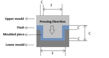
In the compression molding process, more rubber is placed into the cavity than needed, and excess material is squeezed out when the mold is closed. This “flash” prevents perfect closure of the mold halves and affects the final dimensions. For these parts, two types of limit dimensions are defined: dimensions controlled by the mold (F), and those influenced by mold closure (C). Mold-controlled dimensions (F) are fixed, while those influenced by closure (C) may vary depending on flash thickness or misalignment.
Tolerances for Extruded Parts
In extrusion, plastic granules are melted, homogenized, compressed, and pushed through a die using a rotating screw.
As the extrudate often expands upon leaving the die and may shrink or deform during vulcanization, extruded parts typically exhibit greater dimensional variation than molded parts.
Extrusion is used to produce plastic and rubber hoses, tubes, profiles, and sheets. For these, 11 tolerance classes are defined.
Classes E1 (high quality/fine), E2 (good quality/medium), and E3 (standard/coarse) apply to parts extruded without internal support. Parts formed over a mandrel are categorized as EN1 (precision/very fine), EN2 (high quality/fine), and EN3 (good quality/medium).


For hoses, two tolerance classes (EG) apply to the nominal diameter, and two (EW) to wall thickness. EG1 and EW1 refer to precision parts; EG2 and EW2 indicate good quality. The cut length (L) and cut section thickness (EC) are also divided into L1/EC1 (precision), L2/EC2 (good), and L3/EC3 (standard).
Following defined tolerances during production enables components and molded parts to be used and replaced independently of manufacturer and ensures compatibility with existing assemblies, machines, and connectors. Since higher precision involves greater production costs, tolerances should be chosen to be as wide as possible — and only as tight as necessary.
Image sources:
Header image | © NorGal – stock.adobe.com
Tolerance inspection using a digital calliper | © industrieblick – stock.adobe.com