Valves are part of our everyday life – in water taps, bicycle valves, or as 3-way mixing valves in heating systems. The latter regulate the flow rates of liquids or gases and can shut off pipelines completely. For this purpose, they must be precisely designed in terms of construction and dimension. The so-called maximum flow coefficient plays an important role in proper dimensioning.
Understanding the Maximum Flow Coefficient
The maximum flow coefficient (Kv/Kvs in European standards, Cv in US standards) is a key parameter in valve design. It defines how much fluid or gas can pass through a valve under standardized conditions – typically at a pressure difference of 0.98 bar and a water temperature between 5 °C and 30 °C. Engineers use this value to calculate throughput and determine the appropriate valve type and dimensions. In practice, 1 bar is often used instead of 0.98 bar. The flow rate is specified in m³/h or l/min depending on the valve size. For all other media whose density deviates from ρ = 1 g/cm³, the pressure coefficient depends not only on the difference between inlet and outlet pressure but also on the density.
Because gas density strongly varies with temperature, this must also be factored into calculations.
Valves typically operate at different opening levels, known as strokes. Each stroke has a specific flow coefficient, as flow changes with the valve’s opening position. This value helps determine the maximum possible throughput. As a safety margin, engineers typically add a reserve of 20% to 30% to the calculated flow coefficient.
Prior to valve installation, operational parameters must be established to calculate the flow coefficient accurately. These include the desired maximum flow rate, medium temperature, pressure differential, and—depending on the specific medium—its density.
How Does a 3-Way Mixing Valve Work and What Role Does the Maximum Flow Coefficient Play?
While a tap only knows the two end states “open” and “closed,” the valve also allows intermediate positions that enable the regulation of flow between both end states. The usual “water tap” at the sink or in the bathroom is therefore a manually regulated valve at the end of a pipe for drawing water. However, since there are no fundamental constructional differences between tap and valve, a clear distinction is rarely made between both categories, either in common language or in technical applications.


For a 3-way valve suitable for multiple-way cocks, as the name suggests, the flow is regulated on multiple lines – in this case, on three lines with two outlets.
Three-way valves are thus only technical variants of three-way taps. They have three equal ports. The ports are usually at right angles or at an angle of 120° to each other, but other angles are of course possible if required by constructional circumstances. However, it is necessary that the passage holes in the associated shut-off body – typically a ground conical joint for plug valves, a fitted cylinder for cylinder valves, or a precision ball for ball valves – are at the same angle to each other.


Depending on the position of the shut-off body, either the flow is enabled in only one of the two possible directions, the simultaneous flow in both directions is released, or the flow in both directions is blocked. 3-way valves can also be used as mixers for liquids or gases. Here, two of the three ports serve as inlets for one fluid each, while the third port is the outlet for the mixture of both fluids.
Technically equipped three-way valves are used as three-way mixers, for example, for temperature control of heating systems. They allow a predetermined target temperature to be set by mixing the volume flow of the heating medium with higher temperature with the volume flow of the heating medium with lower temperature. A temperature sensor simultaneously measures the current value and compares it with the specified temperature target value to automatically regulate the 3-way mixer via an electronic control unit.
The maximum flow coefficient can be calculated using the parameters of pressure, temperature, and the density of the fluid mixture. However, online tools for determining the maximum flow coefficient or corresponding diagrams from which the flow coefficient can be derived are easier to use.

The Most Important Valve Types and Their Characteristics
3-way valves have become indispensable for the controlled mixing and distribution of liquids, as required in heating systems. Such valves are also needed and used in many other areas where the maximum flow coefficient is a relevant technical parameter.
Flow valves reduce the flow rate of a fluid by narrowing the flow cross-section of the line, thereby reducing its pressure. Such valves are therefore also called throttle valves. They are mainly designed for the regulation of gas flows. Because pressure reduction is accompanied by expansion of the fluid, they are also called expansion valves. In the simplest case, throttling occurs unregulated by narrowing the pipe cross-section, as implemented in refrigerator compressors.

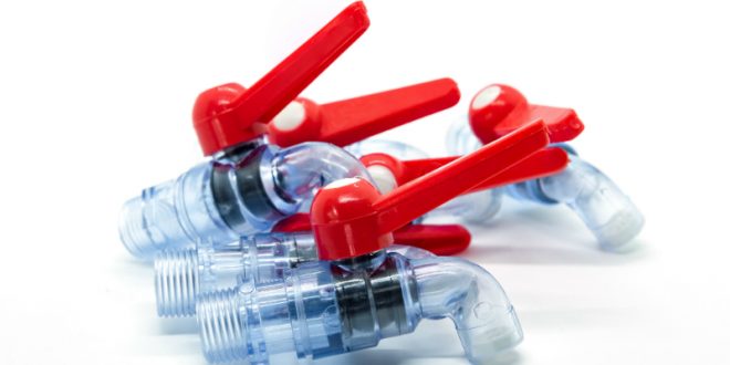
 made of PP")
An important category of valves for mechanical and plant engineering are shut-off valves. These include, above all, quick-closing and quick-opening valves as well as check valves.
Quick-closing valves ensure the abrupt interruption of media flow in a pipeline. Quick-opening valves, on the other hand, are overpressure valves for the immediate opening of a line. Both are mostly used as emergency or safety valves, for example in the chemical industry, to quickly interrupt the flow in pipelines in case of an accident or to open pressurized lines to allow the overpressure to escape in a short time. They can be designed for manual operation, but such valves usually function automatically.


Check valves block the flow in one direction. They prevent the medium from flowing back when pressure drops in the pipeline system. The function-determining closing element of the check valve is usually a ball, but conical shut-off bodies and membranes can also perform this function. They seal the media flow against the flow direction by spring force. Only through the pressure of the fluid is the shut-off body lifted and released in the predetermined flow direction.


The pressure-retaining valve limits the pressure in a line and corresponds in its basic form to a three-way distributor, where one port is closed by the pressure of a spring on a shut-off body or a membrane. If the pressure in the line exceeds the pressure of the locking body, the port opens until the actual pressure is again below the maximum permissible pressure, which can be adjusted by the spring. Such valves are mainly installed as safety valves to safely reduce overpressures. Here too, the flow is determined via the maximum flow coefficient.
Accurate calculation of the flow coefficient ensures proper sizing of 3-way and other valves – and guarantees reliable performance under real operating conditions.